Weekly Progress
Final Update

Week 9 Update
The team had worked extremely hard to make the final revisions and edits to both the design and the final report before the final deadline. The group had also worked to complete a professional poster to present at the Celebration of Engineering event (an event that includes seniors presenting their Senior projects to their faculty and peers). The Honeywalk was one of approximately 12 teams to receive the opportunity to compete with a poster.
With the presentation, final report, final designs and poster completed, The Honeywalk Project was finally complete. It was unclear whether the project would be continued or revisited in the future, but all the group members felt proud of their work accomplished in the short 10 week timeframe.

All group members presenting their poster for competition at the Celebration of Engineering event on June 8th, 2017 in the Bossone Research Center
For further information on the project or interests in continuing The Honeywalk Project, contact any of the group members via email (listed under the “biographies” tab.”. Thank you to all who advised and contributed to this design project.
-------------------------------------------------------------------------------------------------------------Week 9 Update
Part of the Engineering Design III course is during the final weeks of the term, each lab section would nominate a project group to present a poster on their project. This presentation was scheduled to be on the same day as senior engineering presentations at Mitchell Auditorium on June 3rd. The Honeywalk Project was nominated for this honor for section 068. After this nomination, it was determined that a redistribution of roles for the remainder of the project was necessary. The group reserved the beginning of the lab period of Week 9 to discuss a redistribution of roles.
The following tasks must be completed by the following week to successfully complete the course:
- Final Report Submission (revised version of Final Draft)
- Final Blog Checks and Updates
- Presentable model of Honeywalk piece
- Final Presentation
- Project Poster
- AutoCAD drawing of Walkway proposal
Bill was not in attendance for the Week 9 lab (excused absence) but gave Ilana specific instructions for final modifications of model of the Honeywalk piece. Due to the lack of detail for the 3D model (because of the thickness of the 3D printing filament and parameters of the machine), the Fusion 360 model of the surface design as well as several animations for the locking mechanism and legs would be used in the final project. This eliminated the need for a 3D part, confusion regarding the actual design and will be more beneficial for the final presentation.

"Artistic model" of the Honeywalk piece with obvious lack of detail and true nature of design.
The Final report grades were received and there were numerous edits and revisions needed to be made. These include:
- Correct spelling and grammatical errors
- Include more graphics to illustrate design process.
- Analyze results in the discussion section and explain why other designs were unreasonable.
- Making the report more concise (and thus, shorter).
It was decided during the beginning lab meeting that Spencer started the revisions to the final report during the lab period. These edits were to be made available to the group so all could add revisions and discuss proper changes. Spencer was also to complete the Week 9 update and any necessary blog updates/changes prior to the final blog check.
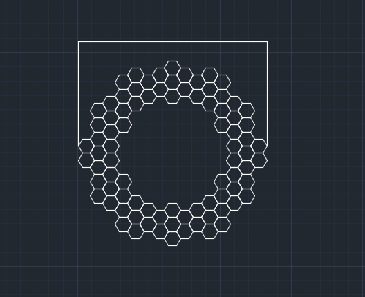
Julia completed the AutoCAD drawing of the Walkway proposal and posted the file in the group folder prior to the Week 9 lab. This included the correction of a dimensions mistake made earlier in the walkway design process (comparison shown in figure below). After this was completed, she volunteered to begin filling in the slide text and graphics according to Spencer’s outline using the draft of the Final Report.

The hexagonal pattern on the left is the corrected design used for the centerpiece of the Honeywalk; the right is a visual of the previous centerpiece.
It was decided that the group members would complete their sections of the Presentation and the entire group would meet Saturday morning (exact time TBD) to finalize the presentation and practice the presentation before the following Wednesday.
Week 8 Update
This week, continued efforts to print the part were made. Issues arose with scaling the size down, as the details were lost in size reduction. No details appeared with the 3D-printed part, and the structurally-sound design was compromised with curling and being too thin.
With the original size of the hexagon being ½ in thick, scaling it down was too much for the printer. Pieces were falling off and detail was lost, in addition to the structural integrity of the piece. No more efforts will be made to 3D print the part, but Ilana and Bill are working in Fusion to develop a visual representation of the hexagon part, in addition to an artistic render of a physical model of the Honeywalk piece. This will not be to scale but will show in detail where the parts would have gone in a 3D-printed piece.
Julia continues to work on the Myers walkway proposal so that a visual of the pathway is created.
 |
| Figure 1: The centerpiece of the Myers Walkway. |
The figure above shows the proposed centerpiece of the Myers Walkway. A tree native to Pennsylvania will go in the center, and all the pathways will connect to this main piece. The dimension shown is to be revised and fixed in the coming week. It was also decided this week that the group would also landscape the rest of the path with native plants and flowers. Spencer spent the day working on the blog updates and finding native plants for the Myers greenspace garden/walkway proposal. These will be made into an annotated list and placed in the CAD drawing so a visual of the garden is created.
It’s important to find plants native to Pennsylvania because these will not die in the summer with hot weather and will return in the spring after the frost in the winter comes. It’s also imperative to find native plants because invasive species are an important factor in the destruction of ecosystems. An accompanying article can be found in Background Information on invasive species.
-------------------------------------------------------------------------------------------------------------
Week 7 Update
The part was attempted to be 3D printed on Monday, May 15th, however there were complications with the printer and its preheating settings and so, the resulting print was incomplete and unacceptable to present.

Printed piece was visually unappealing, incomplete and did not properly represent the proposed design features.
In lab of week 7 Bill and Ilana attempted from a different 3D printer to complete the process. This piece also failed to print properly. It was theorized that perhaps since the piece (in scale) was so thin, the details of the Honeywalk piece were lost. An exact scale model for the presentation was abandoned and the designing of an artistic model in its place was begun. The design would contain all the features of the proposed piece, but with refinements that created a more visually appealing print would be added (for example, making the Honeywalk piece thicker so the 3D printer would have more material to work with).
Spencer and Julia began the AutoCAD designing of the walkway proposal. Spencer attempted to recreate the Myers land plot as best as possible while Julia started arranging the Honeywalk pieces into an optimal transportation path.

Left: Rough CAD sketch of Myers Hall based on scale drawings
Right: Walkway Proposal progress on Myers Hall land plot.
-------------------------------------------------------------------------------------------------------------Week 6 Update

The beginning of Week 6 marked the receival of the original plans involving the building of Myers Hall. Colored in marks the green space that will be created when the building is demolished and it is the space in which our project focuses for a theoretical deliverable.
The space is an area with a perimeter of 12,165.75 inches, or 1,013.8125 feet. The area is approximated to be 893,721.9 ft^2. With this information, group 10 can begin putting together what a potential walkway would look like.
Within the week, one of the members in charge of the plans will be sending a 3D CAD file with the Myers space that will be able to be used in creating a mock-up of the actual design.
Completion of the 3D CAD file of the smaller prototype will be completed by the end of class and will be printed by the beginning of Week 7’s class. Pictures to come.
-------------------------------------------------------------------------------------------------------------
Week 5 Update
Team did not meet outside of lab between week 4 and 5. The 1st 15 minutes of lab in week 5 was reserved for a touchbase meeting with the entire group. The following was discussed.
Bill and Ilana experienced difficulties with the 3D chamfer and fillet options in Fusion 360. They consulted with a more knowledgeable TA who instructed them on how to execute the task. As of lab of week 4, the part is not ready to be printed. It was noted that there was open studio time on Saturdays from 12pm-4pm and on Mondays 9am-5pm. The prototype must be printed by week 6 lab. It was determined that a decision will be made in week 6 whether or not the team will have time to test the prototype load strength in the machine shop, revise the design and reprint before the final presentations.
Due to scheduling conflicts and personal reasons, Spencer and Julia were unable to get to Hagerty library to investigate the books listed in previous update for scale blueprints of the Myers Hall Plot. They committed to meeting early at the library the morning following the Week 5 lab. Spencer updated the blog and took note of Dr. Ellis’ comments on the condition of the blog and components missing from certain pages.
Julia agreed to create a design flow chart to post on the project overview page of the blog during lab time while Spencer elected to finalize the walkway application proposal timeline and prospective budget, the actual budget for the entirety of the Honeywalk Project (creating the prototype, scale model of walkway, illustrations, materials, etc), and the week 5 update. Bill and Ilana continued to improve the Honeywalk piece design.
The meeting lasted 20 minutes; afterwards, the team split up to work on their assigned tasks.


Left: Julia creating a design flowchart to post on blog. Spencer using the scale drawings received from James Rose to recreate the Myers Hall plot.
Right: Bill (left) and Ilana (right) navigating Fusion 360.
Note: The group is approximately 1 week behind schedule as of week 5.
-------------------------------------------------------------------------------------------------------------
Week 4 Update
A few big changes to the project were made in week 4. Group 10 decided on a thickness of ½ an inch for the plastic for the full-scale model, as there was a large difference in cost when mass-produced. The costs were predicted to decrease further if Drexel was to cut out purchasing from a 3rd party plastics manufacturer and form a partnership with a plastics recycling facility (or develop their own). This would lower the overall cost of product and shipping expenses. It would also open the opportunity for Drexel to recycle its own plastic waste.
Also decided in week 4 was postponing the proposal for the Myers Walkway, as no one in the group had access to any exact measurements (from measurements taken in the field or data accessible online). After using lab time to perform research in the library database, several book options that may contain illustrations and scale drawings of Myers Hall were uncovered. Spencer saved these to his library profile and will go to W.W. Hagerty Library to research further.
The list of books included:
[1] Drexel University. Department of Planning and Construction. Building floor plans for drexel university. Building Floor Plans for Drexel University 1974.
[2] M. N. Kotzin. A History of Drexel University, 1941-1963 1983.
[3] Drexel University. Housing Restudy Committee and Nolen and Swinburne Partnership. Housing Study for Drexel University 1971.
Uncovering scale blueprints of the building was decided to be faster, more accurate and more precise than performing field measurements with inadequate tools; drawings reduce possible error in reproduced CAD drawings of the building tremendously, and will bolster the reality of the project proposal. Several important factors will be included in the final walkway proposal.
It was decided that the walkway proposal would contain the following components: approximate budget post-demolition of Myers hall, bill of materials, project timeline, and AutoCAD drawings of the walkway. It was unclear if the team would have time to create a scale model of the walkway proposal or not. This decision is to be brought up again in week 7.
Bill and Ilana continued to work in Fusion 360 to sketch the model of the first draft. It was determined that it would be doubtful that the model would be ready to print by week 5, but will continue to be worked on in hopes that it could meet the deadline.
Week 3 Update
In week 3 lab, the group decided on changes to the timeline. Rather than buy sheets of plastic used only for testing strength purposes, group 10 decided to forgo this step and test on 3D printed models instead.
The total estimated size from corner to corner of the surface hexagon was estimated to be approximately 3.4641 feet, or 41.569 inches, so the scale model was determined to be of 1/6th scale, residing at a comfortable 3D printed model that measures 6.928 inches corner to corner.

The group also decided that instead of just doing the 3D printed models and strength-testing them, to take up the now free area of time after the models are printed, the group will determine what a potential pathway through the Myers Hall green space project would look like.

Myers Hall, built in the 70’s, worked as temporary housing at Drexel University. It is to be torn down in 2018 and replaced by an urban green space in which students can relax and do homework. The proposed walkway would utilize the Honeywalk project in a real-life application and give a visualization of how the walk would work.
The revisions made to the project timeline, goal, and deliverables should bring the group to the end of week 10 with a real-life application for presentation. It was determined that Spencer edit the project timeline to adjust for the deliverables.
Goals for the next week were determined to be the following: Julia and Spencer sketch a mock-up of the proposed walkway and begin CAD designs, Ilana and Bill begin to sketch 3D model in AutoCAD or Fusion 360 (including locking and lowering mechanism).
-------------------------------------------------------------------------------------------------------------Week 2 Update
Group meeting was held in the Library Learning Terrace on (04/11) to discuss project proposal due in following lab. Possible designs that were sketched in Fusion360 were discussed. One design, shown in Figure 1, was a proposal for the interlocking mechanism of the Honeywalk pieces. It was brought up that, although functional and easy to reproduce, attach and detach, it would be required to design an additional ramp piece for the Honeywalk so it could be handicap accessible. Hence, that design was rejected.
Roles for the design proposal and first blog check were as follows:
-Julia: Abstract, Technical Activities, Budget, Deliverables
-Ilana: Introduction, Facilities and resources
-Spencer: Set up group gmail account for Blogger, construct blog design, materials costs research, Project Timeline
-Bill: Introduction, Expertise
After Dr. Ellis spoke to the group on the project in Lab 2, it was suggested to print several scale models in the printers available in the lab rather than access the machine shop with materials that the machinery may not work on. The group decided to make several ⅓ scale models of the Honeywalk pieces. Recycled HDPE plastic will still be ordered, in a smaller quantity, and used to test properties of the recycled plastic.
Lab 2 was used mainly as a research period. Bill continued to work on the locking and folding mechanism for the Honeywalk pieces. Julia revised the Blogger. Ilana and Spencer split the research needed between the two of them (current walkway construction, strengths and properties of recycled plastics, and greenspaces in urban settings).
Budget and Project timeline needed to be adjusted for changes made in lab.
Exact dimensions of Honeywalk pieces were not yet confirmed, as Bill was unfinished with locking mechanism needed for the pieces.
-------------------------------------------------------------------------------------------------------------
11 April 2017
Finalized Weekly Timeline for Spring Term 2017 Project (to take place bettwen 03 April 2017 and 12 June 2017)
-->
| Week 1 | Week 2 | Week 3 | Week 4 | Week 5 | Week 6 | Week 7 | Week 8 | Week 9 | Week 10 | |
| Course Checkpoints | ||||||||||
| Form Group | X | |||||||||
| Blog Check #1 | X | |||||||||
| Design Proposal | X | |||||||||
| Blog Check #2 | X | |||||||||
| Final Report Draft | X | |||||||||
| Blog Check #3 | ||||||||||
| Final Report | X | X | ||||||||
| Final Presentation | X | X | ||||||||
| Research | ||||||||||
| Research current walkway construction | X | X | ||||||||
| Research strengths of recycled plastics | X | X | ||||||||
| Research greenspaces in urban settings | X | X | ||||||||
| Design | ||||||||||
| Define dimensions of Honeywalk pieces | X | |||||||||
| Order plastic sheets for full scale piece | X | |||||||||
| Design locking mechanism | X | |||||||||
| 3D designs in AutoCAD | X | X | ||||||||
| Print scale 3D parts | X | X | ||||||||
| Test load strength of recycled plastic | X | X | ||||||||
| Design revisions and reprint (if necessary) | X | X | X | |||||||
| Build 1/3 scale piece | X | X | X | |||||||
| Deliverables | ||||||||||
| Final 3D Printed Parts | X | |||||||||
| Final Blog updates | X | |||||||||
| Final Presentation | X | X |
-------------------------------------------------------------------------------------------------------------
Project Flowchart


Be sure to include budget and flowchart like that found on the facts and figures tab of this website: http://du2016-grp065-02.blogspot.com/p/timeline.html .
ReplyDeleteBe sure to include images for the weekly updates - can show the team working, what you've developed, or diagrams of your invention, for example. I like the hexagon diagram showing the relative scales of the actual size and the prototype size a lot.
Still more images of the team working needed.....
ReplyDelete